
When a Stage III vapor recovery unit reports a low recovery rate while its own components check out, the restriction is usually in the vapor path between the storage tank and the unit. Pressure drop is cumulative: every elbow, reducer, partly closed valve and condensate trap adds to it. A system sized from pipe length alone, without allowing for fittings and liquid, tends to underperform from the day it is commissioned.
Where the loss accumulates
The route from tank to unit passes through more than pipe. There are tank nozzles, the connection into the vapor header, changes of direction, valves, a flame arrestor where fitted, the liquid trap, and the final connection into the unit. Each of these contributes a fixed loss that does not scale with pipe length, and on short runs the fittings can account for a larger share of the total than the pipe itself.
How to trace a restriction
- Record the vacuum at the unit inlet and at the tank end under the same operating condition;
- Divide the route into sections using valves or accessible points, and measure the difference across each section;
- Inspect the accessible low points and the liquid trap for accumulated liquid;
- Check every valve position against the commissioning record before assuming a blockage;
- Look for sagging sections where the pipe has settled, since these form liquid pockets;
- Compare the measurements with the commissioning data to see whether the loss is new or was there from the start.
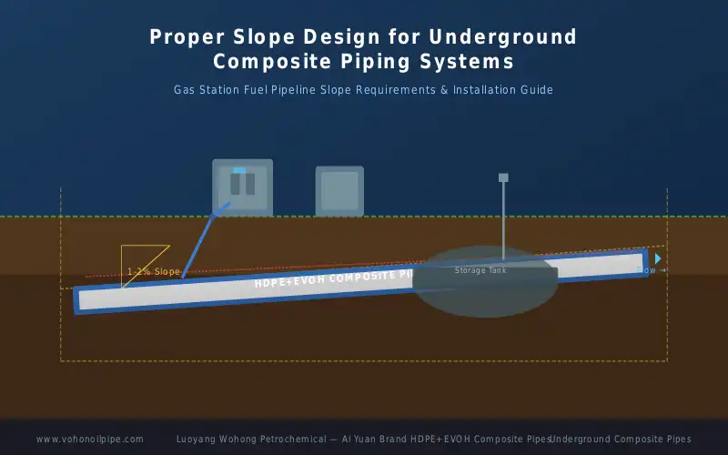
Slope, settling and liquid traps
A vapor line should drain in a defined direction, normally back toward the tank or toward a dedicated trap, without a local low point that collects condensate. Pipe that settles after backfill can create exactly such a low point, and the result is a pocket of liquid that the blower has to pull past. This is why slope verification during installation, and a check of the profile after the forecourt has been completed, is worth the effort.
Symptom to cause
| Symptom | Likely location | Check |
|---|---|---|
| Steady low recovery rate from commissioning | Undersized route or too many fittings | Compare design allowance against actual layout |
| Recovery falling gradually over months | Liquid accumulation at a low point | Inspect trap and the lowest accessible section |
| Vacuum high at unit but normal at the tank | Restriction between the two points | Split the route and measure section by section |
| Intermittent loss of vacuum | Partly closed valve or moving liquid slug | Verify valve positions and check for slugs |
Design habits that prevent the problem
Allow for fittings and traps when sizing the vapor route rather than counting pipe length only; keep the number of direction changes to a minimum; specify supports and bedding that will not allow the line to settle into a dip; and record the vacuum readings at commissioning so that a later change can be measured against a known baseline rather than against an assumption.
Common questions
Can a restriction be cleared without excavation?
Sometimes. Where the cause is a closed valve, a blocked trap or liquid in an accessible chamber, the problem can be resolved from the surface. Where pipe has settled to create a low point, correcting the profile means exposing that section.
How much pressure drop is acceptable?
There is no universal figure, because it depends on the blower, the route length and the control band the system is designed to hold. What matters in practice is that the allowance was made during design and that the commissioning readings are recorded so future changes can be compared.
Does pipe diameter solve everything?
Increasing diameter reduces the loss along the pipe, but it does nothing for the losses at fittings, valves and traps, and it can make liquid accumulation worse if slope is poor. Diameter is one variable among several.
Luoyang Wohong Petrochemical Equipment Co., Ltd. supplies double-wall composite fuel piping, fittings and electrofusion accessories for gas station and fuel depot projects. Contact us for pipeline layout review and product selection support.