
Short answer: the conductive layer in a composite fuel pipe exists to carry static electricity, which every flowing fuel generates, from the wall of the pipe to a real ground path instead of letting it accumulate on an insulating plastic surface. Gasoline moving through a hose or line separates charge the way a sweater pulls static in dry weather, and in fuel service that static has exactly the wrong neighborhood: vapor spaces where an energetic spark can ignite hydrocarbon air mixtures. Steel pipe solved the problem by being conductive all the way through. Thermoplastic pipe solves it deliberately, with a dedicated conductive layer bonded into the wall and connected through fittings and hardware to the site grounding system.
Where the static actually comes from
Static generation in fuel service is not exotic; it happens at every transfer. Product rushing through a line, filtering through a dispenser, splashing into a tank or tumbling through a delivery hose all shears charge apart at the fuel surface, leaving the liquid and the surfaces it touches at different potentials. Most of the time the charge recombines harmlessly or drains away through anything conductive it can reach. The danger case is specific and well understood: charge accumulates on a surface that cannot conduct it away, builds until the local field is strong enough, and releases as a spark across a vapor space. Fuel handling rules everywhere therefore share one theme, which is to give every charged surface a continuous, low resistance road to earth.
What the conductive layer does inside the wall
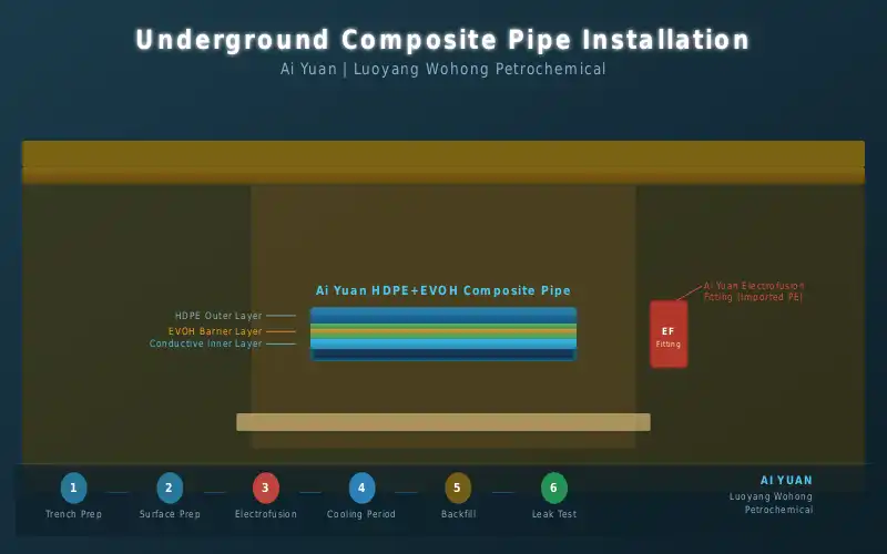
A composite fuel pipe is a laminate, and the conductive layer is one of the functional plies sitting beside the structural and barrier layers. Conductive masterbatch turns that ply into a distributed electrode running the whole length of the pipe, so charge that reaches the pipe wall has somewhere to go: it spreads into the layer and travels along it toward any point where the layer is connected to ground. The layer inside the wall also means the outer surface, which installers and inspectors actually touch during the job, is not an isolated dielectric waiting to hold charge. The multi layer co-extrusion guide shows how the conductive ply sits among the other layers and why co-extrusion is what makes the arrangement continuous rather than patched.
The path to earth is the whole system, not one layer
A conductive ply inside a wall does nothing on its own; it needs continuity from the fuel side all the way to the grounding system, and that continuity is built from several parts working together:
| Element | Role in the static path | What breaks it |
|---|---|---|
| Conductive inner surface | Collects charge at the product wall | Oxide or contamination left at joints |
| Conductive layer in the wall | Carries charge along the pipe | Cut or abraded ply at a field joint |
| Electrofusion fittings | Bridge the layer across every joint | Fittings without matched conductivity |
| Transition hardware at sumps | Connect the buried run to site bonding | Paint or corrosion isolating the contact |
| Site grounding system | Dissipate charge into the earth | Unverified or undocumented ground rods |
Reading the table from top to bottom explains a habit that experienced installers keep: they treat static continuity as a circuit and check it as one. Any single gap, a scraped ply left unbridged, a fitting from a mismatched system, a bond point hidden under paint, is enough to turn the rest of the good work into an isolated island that charge cannot leave.
Why HDPE alone would not be safe
Plain high density polyethylene is an excellent pressure vessel material and an excellent insulator, and the second quality is the problem. A pure HDPE line carrying gasoline would behave like the hose of a vacuum cleaner on a dry day, quietly charging its own surface with nowhere to discharge. Structurally the pipe would last its decades; electrically it would be a capacitor buried beside fuel vapors. This is why fuel grade composite products differ from generic plastic pipe not only in barrier technology but in electrical design. The two features travel together in serious systems: the EVOH barrier stops vapor and fuel diffusing through the wall, and the conductive structure gives static a controlled exit. The barrier layer guide covers the permeation side of that pairing.
Installation habits that keep the static path alive
The conductive design survives construction only if the crew honors it, and the habits involved cost minutes rather than money:
- Scrape and clean every fusion surface fully, because the conductive ply must be exposed and matched at each joint, not insulated under a residual oxide film;
- Use electrofusion fittings from the same system as the pipe, since the conductivity bridge across a joint is part of the fitting design rather than an accident;
- Verify bonding hardware at every sump and riser, cleaning contact surfaces to bare metal and recording each bond point on the as-built drawing;
- Keep the grounding system testable, with accessible points where a resistance measurement can be taken at commissioning and again at inspections;
- Never substitute generic fittings or cut the conductive structure in the field without re-establishing continuity, because a shortcut at one joint defeats the whole route.
Crews that work this way produce lines where the static path can be demonstrated, not just presumed, and demonstration is what a thorough inspection asks for.
Static safety and vapor recovery as one design
On a modern forecourt the static story extends past the product lines into the vapor side. Return lines carry hydrocarbon rich vapor, which is the flammable half of the hazard pair, and they are built from the same composite system with the same conductive expectation. Stage III processing ties the whole network together at the tank vent, and an inspection of static readiness therefore walks the complete loop: dispenser bonding, transition hardware, buried runs, sump contacts and the vent connections where the vapor system hands over to processing equipment. The inspection checklist at the sister site sequences that walk, and it is a sensible companion document for any contractor wiring a new composite network into an existing recovery system.
The takeaway for buyers and builders
Static safety in a composite piping system is designed in and installed in, never assumed. The conductive layer is the quiet feature that lets a plastic pipe do the job steel once monopolized, and it asks only that the system around it, fittings, bonds, grounds, be kept continuous and documented. Buyers comparing products should ask how conductivity is achieved and proven; contractors should treat every joint as a place where the path can quietly die. Handled this way, the conductive layer does its work invisibly for the life of the station, which is precisely what a safety feature should do.
Frequently asked questions
How is conductivity in the pipe verified on site?
Through continuity measurement across the installed system, taken between accessible conductive points such as transition hardware and bonding terminals, and by confirming each joint used conductive matched fittings. Records of these measurements belong in the handover documentation alongside weld records.
Does the conductive layer replace site grounding?
No, it feeds it. The layer collects and transports charge, but dissipation still requires the site grounding system to be present and sound. The two are designed together, and a conductive pipe bonded to a dead ground is an insulated pipe with extra steps.
Is the conductive layer the same as the EVOH barrier?
They are different plies with different jobs. EVOH blocks vapor and fuel permeation through the wall; the conductive layer manages static. Serious fuel pipe carries both, and neither substitutes for the other in the wall structure.
Static discipline extends to the vent and vapor side of the site, and the vacuum integrity notes show how the return line and the conductive structure work as one system.
Luoyang Wohong Petrochemical Equipment Co., Ltd. supplies double-wall composite fuel piping, fittings and electrofusion accessories for gas station and fuel depot projects. Contact us for pipeline layout review and product selection support.