
Short answer: seismic design asks an underground composite fuel pipe network to do three things a normal specification does not: survive ground deformation without losing joint tightness, keep every connection to tanks and dispensers restrained through shaking, and fail in ways that are detectable rather than catastrophic. Composite pipe starts with a real advantage here, because a flexible thermoplastic line with electrofusion joints absorbs movement that would crack a rigid threaded system. But advantage is not automatic. Anchorage, routing, joint placement and monitoring all have to be planned with the seismic setting in mind, and the sites that do this well treat the earthquake as a design input from day one rather than a hypothetical for the appendix.
Why seismic zones treat buried fuel systems differently
An earthquake does three things to a buried network at once. The soil around the pipe compresses and releases in waves, so the line is squeezed and pulled along its length. Where the ground is stiff in one place and soft in another, the two bodies of earth move differently and the pipe is dragged between them. And at the ends of the system, where the pipe meets heavy rigid objects such as tank sumps and dispenser housings, the light flexible line is tied to masses that move on their own rhythm. Most earthquake damage to buried utilities happens at exactly those interfaces, which is why seismic design concentrates less on the middle of the run and more on the ends and transitions.
What the material itself brings to the table
A composite fuel pipe deforms instead of breaking, and that single property changes the failure pattern of the whole network. Steel lines in strong shaking tend to concentrate stress at welded or threaded connections, where a small angular offset becomes a tear. A thermoplastic line bends through the same offset and returns. Coil based product is especially forgiving, because the natural curl of the pipe gives the run a stored geometry that absorbs longitudinal shift. None of this means the line can be treated as unbreakable; overstretching a joint, folding the pipe through a kink or letting it bear against a hard trench edge can still create weak points. The honest summary is that the material removes one class of failure and keeps the responsibility for the rest with the installer.
Where seismic load actually lands on a fuel system
Reading the network as an engineer does, the components that need seismic attention are predictable, and it is worth naming them before the design is fixed:
| Component | Seismic behavior | Design response |
|---|---|---|
| Long straight runs | Move with the soil wave, low local stress | Normal bedding, avoid hard points in the trench |
| Tank sump connections | Heavy tank and light pipe shake differently | Flexible entry geometry, restraint at the sump |
| Dispenser transitions | Above ground mass tied to buried line | Movement allowance in the riser and transition |
| Electrofusion joints | Strong in tension and compression | Keep joints away from abrupt stiffness changes |
| Vent and vapor lines | Long thin runs, easy to whip at supports | Support spacing reviewed for lateral motion |
The pattern in the table is consistent across seismic guides for buried utilities: protect the interfaces, let the body of the line float. The anchoring and support guide covers the restraint hardware in detail, and the same principles carry over with higher margins in seismic settings.
Routing and trench planning that add resilience
Before any hardware is bought, the drawing itself can remove most of the seismic risk. Poor plans route the line across abrupt soil changes, tie every branch into one rigid node, or leave no room for the pipe to move where it must. A seismic aware planning pass looks like this:
- Mark the soil profile along the route and flag every place the trench crosses between native ground and engineered fill, because those crossings are where differential movement concentrates;
- Prefer gentle curves and generous bend radii over right angles, so imposed movement spreads along the run instead of piling up at one fitting;
- Break large networks into hydraulically separate sections with isolation valves, so damage in one zone cannot drain the whole site;
- Keep joint clusters away from sump entries and risers, placing the electrofusion fittings in soil that moves coherently;
- Specify bedding and backfill that match the surrounding ground stiffness, avoiding a soft pillow beside compact bases that would force the pipe to bridge the difference.
None of these steps costs more than a little drawing time, and each one removes a failure mechanism that no hardware can fix after the trench closes. Sites in known seismic belts should treat the list as mandatory rather than advisory.
Joints and connections: the part that decides the outcome
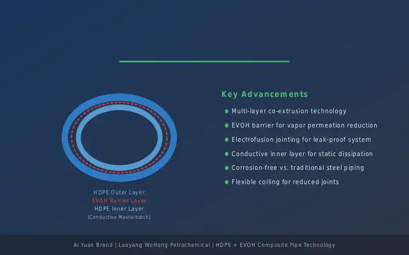
Experience with buried utilities in earthquakes keeps repeating one lesson: the pipe survives, the connections decide. For a composite system this cuts in your favor when the joints are done properly. An electrofusion joint that has been scraped, cleaned, clamped and allowed its full cool time develops strength across the joint zone that lets the line move as one continuous body, and the flexibility of the joined system then becomes real. A rushed joint does the opposite; it turns the flexible advantage into a stiff spot with a hidden flaw, and strong shaking finds such spots without mercy. This is why seismic specifications in practice lean heavily on joint quality documentation, and why the records habit matters more here than anywhere else. The seasonal ground movement guide explains how the same connection discipline pays off in ordinary soil motion.
Monitoring and the recovery plan after an event
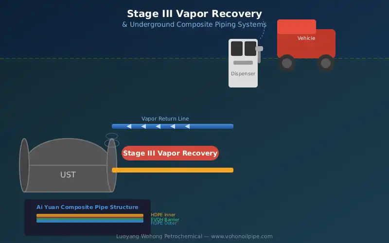
Seismic design does not end at the trench. A station in an earthquake belt needs an answer to the question of what happens the morning after a significant event, and the answer should be written before it is needed. Double wall systems with interstitial monitoring hold a strong position here, because the annulus gives the operator a way to check containment integrity without excavation: pressure or vacuum held in the monitoring space after the event is meaningful evidence that the product wall survived. Single wall sites lean on line tightness testing, sump inspection and dispenser connection checks. Either way, the recovery plan should sequence the checks and define what result puts the line back in service. The double wall lifecycle comparison includes the monitoring argument, and in seismic regions that column carries extra weight.
Bringing the seismic input into a normal project
None of this turns a station build into a special engineering exercise. The composite system that suits any modern forecourt also suits a seismic one; the difference is that the seismic site documents its movement allowances, restraint hardware and joint records with more care, and plans its inspection routine around the possibility of an event. Those qualities pay back in ordinary operation long before any earthquake arrives, which is the quiet reason seismic practice and good practice overlap so heavily.
Frequently asked questions
Is composite pipe better than steel in an earthquake?
For buried fuel service, generally yes, because flexibility moves stress away from the joints that fail first on rigid systems. Steel still performs well where its supports and welds are engineered for the motion, but on a normal station budget the composite system reaches seismic resilience more naturally, with fewer special interventions.
Do joints need special fittings in seismic zones?
No separate fitting family is required, but placement and quality control tighten up. Electrofusion joints should sit in coherent soil away from stiffness transitions, and documentation of each weld becomes more valuable because the network may one day be asked to prove its integrity after shaking.
How do you check a buried fuel line after an earthquake?
Sequence a visual inspection of sumps, dispensers and vent terminations, then verify containment: annulus pressure on monitored double wall lines, or a line tightness test on single wall systems. Return product flow to service only after the containment result is on record, and investigate any monitoring anomaly before reopening the zone.
Recovery planning pairs the piping checks with the processing side, and the Stage III obligations overview at the sister site frames what regulators expect a station to hold after an unplanned event.
Luoyang Wohong Petrochemical Equipment Co., Ltd. supplies double-wall composite fuel piping, fittings and electrofusion accessories for gas station and fuel depot projects. Contact us for pipeline layout review and product selection support.